HP Series 80 PRM-85
PRM-85 - Casing
The PRM-85 is supplied as an assembled board, and can be plugged straight into a Series 80 expansion socket. However, some users may wish to house their PRM-85 in a case, to make it appear like the original Programmable ROM Module.
The latest boards are version 1.1, these do not require much effort to fit in a standard interface module case.
These notes describe how to fit the earlier version 1.0 board shown below into the case from a Series 80 HP-IB module.
This version of board requires some minor alterations to the PRM-85 board and to the module case, using the following:
- Drill with 6mm and 7mm diameter bits
- Sharp craft knife
- Sand paper or similar
- Insulating tape
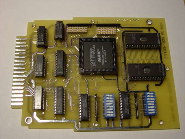
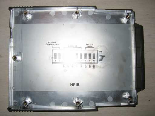
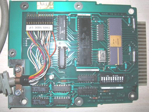
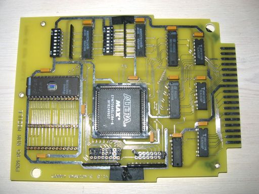
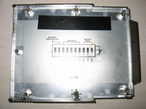
The following shows the PRM-85 and the module case before making changes (except I had already drilled out the PCB mounting holes!).

The following problems prevent the version 1.0 PCB from fitting into the module case as is:
- The module PCB is located in the case mainly by the two mounting holes, shown in the top photograph in the top-right and bottom-left corners of the PCB. On the original PCB these holes were roughly 5mm in diameter, which was too small to fit the locating lugs of the case.
- Near the top-middle hole of the PRM-85 PCB there is a black resistor pack, this pushes against the corresponding lug on the module case so the PCB is pushed out of alignment.
- The HP-IB case (like other module cases) is spayed with a conductive metallic coating. There is a risk this would short out the PRM-85 circuit as the PCB tracks pass very close to the mounting holes.
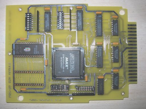
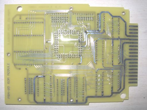
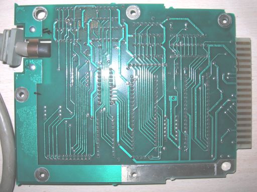
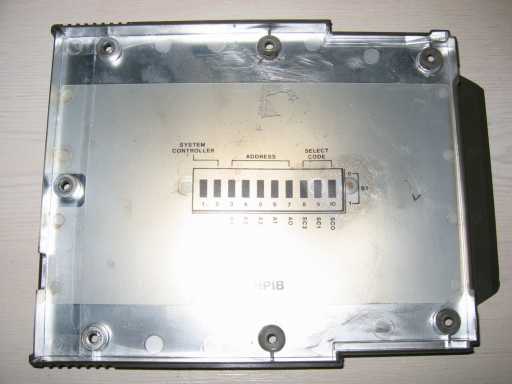
For comparison here is the HP-IB module PCB.
The modifications needed are as follows:
- Carefully enlarge the two corner locating holes on the PRM-85 PCB from 5.5mm to 7mm diameter. I would recommend great care here, and suggest firstly drilling out to 6mm. Then rotate the drill at an angle to increase the hole size slightly, and finish off with a 7mm bit vertically. Do not force the drill to avoid cracking the PCB.
- Cut away most of one of the middle lugs in the top half of the module case, so that the board will fit and the case can be closed without it fouling on the black resistor pack.
- Sand the conductive silver paint away from the mounting lugs in both halves of the module case.
- Cut and attach insulating tape to the PRM-85 in areas near the mounting holes where there are PCB tracks.
- Cut and attach insulating tape to the top half of the module case above where the PRM-85 jumpers are located.
- The metal bracket fitted to the HP-IB module is not required and must be removed.
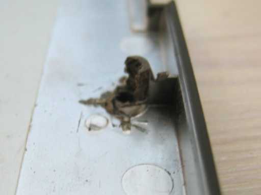
Here are the finished items.
Here is a close up of the remains of the mounting lug (bottom-middle on photograph above).
Check that the case fits neatly over the PRM-85, and test it out in your Series 80 machine before screwing the case back together.
As a final touch fit a label of your choosing!
This page was last revised on: 12/04/09